Slow couple of weeks – and a Flying Scotsman!

I’ve been taking a break over the Australia Day holiday – and waiting for some bits and pieces to arrive from China, namely servos and servo extension leads to finish the project.

In the meantime, I’ve made up the remaining five servo mounts which I purchased from Brunel Hobbies. I’ve got to purchase some clevises and pushrods because three of the remaining servos are to be mounted in a restricted space, though they’ll only be an inch or two away from the spot they are needed.

I purchased the Hornby Flying Scotsman with DCC Sound yesterday too when I was in the shop and have had it running around and around on the track choo-chooing and whistling away. I’m such a kid!

How it all works

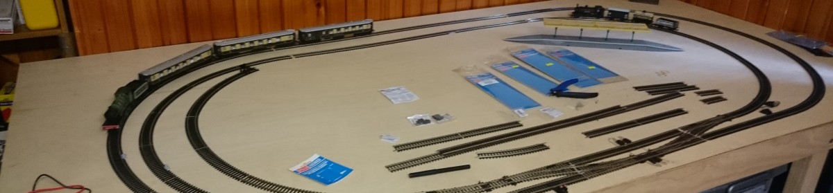
Let me see if I can explain how I figured out how it works so I could wire it up.

ThreeWayPoint

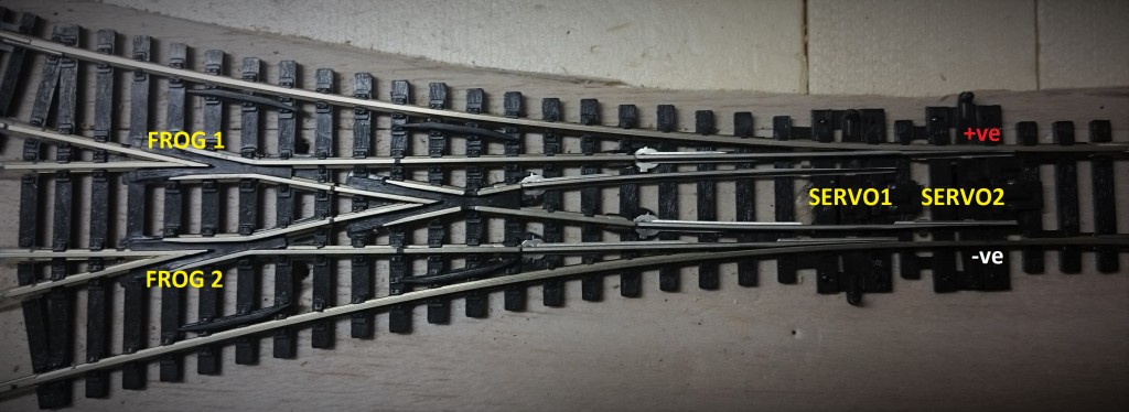
I’ve nominated the lower track to be negative (-ve) and the upper track to be positive (+ve) for the sake of this discussion. So long as they don’t short circuit, everything comes up roses.

Servo1 and Servo2 drive the points. Frog1 powers the centre and the right-hand turnout. Frog2 powers the centre and the left hand turnout.

There are three possible values for the position of the servos as set out in the table below (You cannot have servo1 up and servo2 down). I have written down the required polarity of each frog based on which turnout is active.

Servo position ↑ ↑ (left) ↓ ↑ (centre) ↓ ↓ (right)
Frog 1 n/a +ve -ve
Frog 2 +ve -ve n/a

When the turnout is in the left position (↑↑), the polarity of FROG1 is unimportant. Likewise when the turnout is in the right position (↓↓), the polarity of FROG2 is unimportant.

It can be seen that there is a relation between Servo1 and Frog 2 and between Servo2 and Frog1, such that

Frog1 polarity must be +ve when Servo2 is up and -ve when Servo2 is down.
Frog2 polarity must be +ve when Servo1 is up and -ve when Servo1 is down.

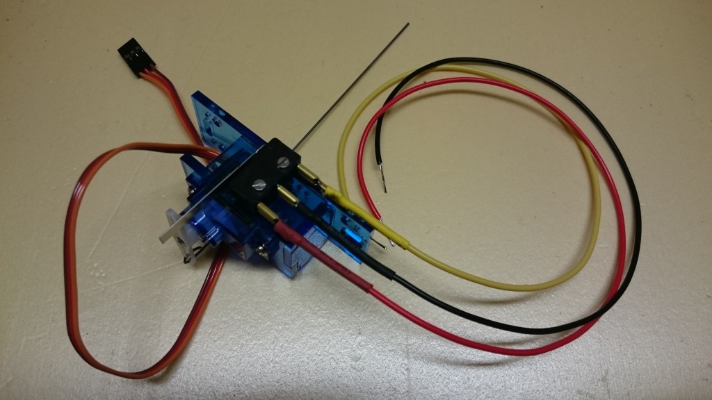
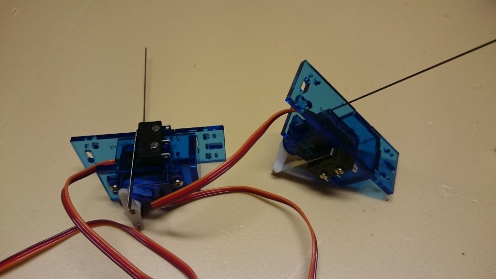
The microswitches attached to the servos are activated when the servo has moved the switch to the right. This gets a bit tricky now because I have the servos mounted facing each other, not back to back, so that there’s plenty of room to work with them.

The microswitches have three pins. two of them are connected to +ve and -ve inputs. The third pin is the output and will be either +ve or -ve depending on the state of the switch. I mapped which pin would be active on the switch based on the position of the servo in relation to the track.

Servo position
Servo 1 microswitch pin active pin 1 pin 2
Servo 2 microswitch pin active pin 2 pin 1

I determined that when Servo1 was in the up position, it’s microswitch was connecting pin 1 to common. As the servos are reversed in relation to each other, the opposite it true of Servo2.

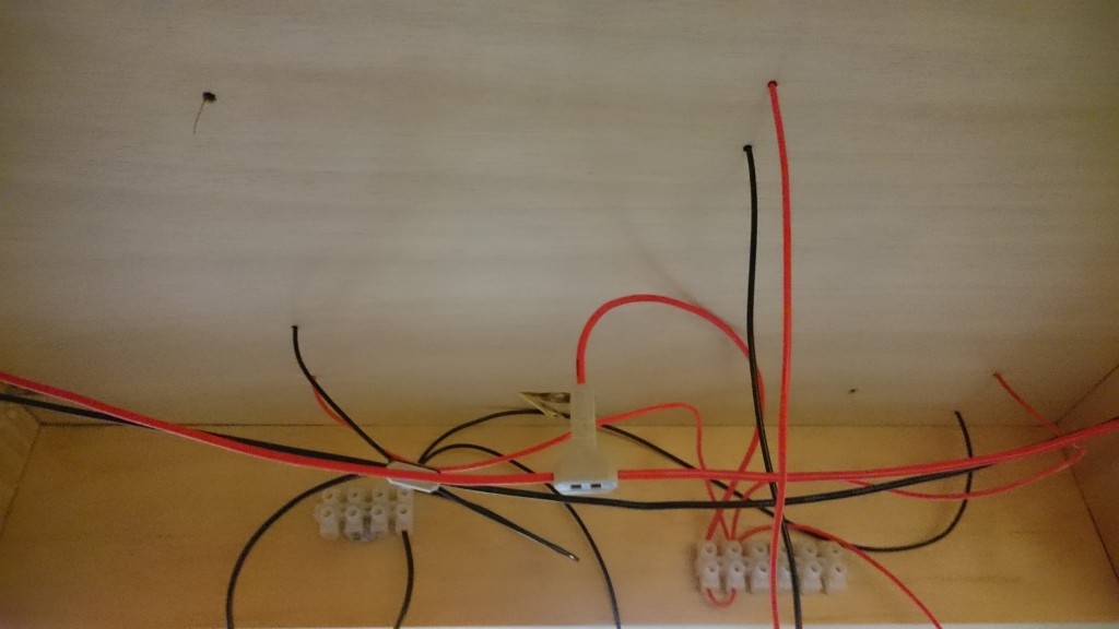
The microswitches are wired as follows:

Microswitch pin 1 pin 2 pin 3
servo 1 connected to Frog 2 +ve -ve common
servo 2 connected to Frog 1 -ve +ve common

So, for example, when both servos are thrown to the left, the turnout is to the right, and Frog1 needs to be -ve polarity. Frog1 is connected to the microswitch on servo2 which is down, so pin 1 is connected to common so the frog is -ve.

Wiring the microswitch

I’ve made three wires to attach to the microswitch – red and black are the inputs and yellow is the output. When the switch is open, the yellow wire will be one polarity and when closed it will be the other. If it’s the wrong way around, I’ll simply swap the black and red wires (which are thankfully the easiest two to get to)

The black and red wires take their input from the DCC bus. The yellow wire will go to one of the frogs on the three-way turnout.

Microswitch leads

To determine which wire goes where, I drew a diagram which showed all the parts and then calculated the frog polarities. Each of the frogs is powered from one microswitch.

Servos and octopuses

Yesterday I took the plunge and purchased a couple of servos, a TAM Valley Octopus IIIa Servo Driver, switches and a remote aligner. I’ve started putting it all together – the servos are mounted in their brackets and I have cut and bent the piano wire onto them.

Servos

I’ve removed the springs from the point that I’m going to wire up also so it’s all ready to go. I’m seriously considering putting a 10mm brass sleeve inside the hole for the servo wire to pass through. I will get onto it later today when I have some time – I have some other things I need to attend to first.

Electrifying the layout – first go

This morning I broke out the soldering iron and resurrected my long disused soldering skills attaching wires to the track. I used T-clips to break into the bus wires I’d strung under the table and connector blocks to take the current to the track. It worked first go and the train went the whole way around … on the outside track.

The other tracks are a bit hit and miss I’m afraid. All those insulator connectors, and I suspect one of the T-clips or connector blocks has not worked as expected as all of the track connected through them remains unpowered.

The three way turnout is going to be a problem too until I get power to the frog – which I suspect means I’ll have to wire it up fully. The single turnouts are easy – the frog takes power from the line which is touching.

Edit: The power problem was in a T-Connector but I just hadn’t seated the wire properly. Five minutes with the multi-meter was all it took to narrow it down.

Train Wiring Under Table

Drilling holes for the points

Today’s task is drilling holes through the foam & plywood top for the servos to activate the points. I’ve got a few weeks before the kit is in to wire them up, but best to do it now rather than try to pull the layout apart later.

I’ve used a felt tip pen that I can poke through the hole in the point to mark the location (moving the point from side to side) and then I’ve drilled a 10mm hole using a spade bit. I’m also drilling small holes to take the wires which electrify the frog.

The 10mm spade bit has made a bit of a mess (heh) but it should be ok once the track is in place and it’s all covered up. I used a 2.5mm drill bit in the dremel to make the holes for the frog & power lines which I will solder to the track tomorrow. I didn’t get as far as I wanted today, but tomorrow’s another day!

I’ve bought some connector blocks which I’ll wire together to make a local bus connection. Pics tomorrow.

Foam under the underlay

Did you ever have one of those “aaaaaargh” moments?

This morning I went back to the model shop to get some more track underlay to complete the layout and I got talking about my setup. I mentioned that the underlay had really quietened the running and it was then suggested that I use insulating foam under it all to really make it quiet.

Initially I was hesitant because it meant lifting all the track & underlay up, putting down the foam and starting again, but the more I thought about it, the more it seemed like a really sensible thing to do. I looked up the foam and found it at Bunnings for $12/sheet at 1200×600. My layout is 1200×2400 so I need four sheets… but wait… my layout is actually 1220×2440 courtesy of the sheet of plywood I used as a table top… so I will need five so I have one to cut up for edges!  I guess I can use what’s left to make a small hill sometime!

The big advantage of the foam, other than the noise deadening qualities, is that I can pin the track to it easily. Thinking ahead, I’m also going to be able to plant trees and stuff in it easily without have to resort to drilling holes in the plywood every time.

I managed (with a little help from my daughter) to slide it underneath the layout without too much trouble and here’s the result:

Layout On Foam

The two branch lines which finish in the centre are not yet complete.

I’ve used balsa underneath all of the points instead of underlay as advised.

Track laying time – underlay

So yesterday I bought the last few pieces of track needed to complete the layout. I’ve ended up with a whole bunch of radius pieces that I’m not using – not sure how that happened but I guess I can save them for the next track 🙂

I’ve decided to nail down the track over foam rather than glue it down. Glue is fine for stuff that you never want to change, but I’m not so sure that the layout will stay the same forever. Also, if I find that I’ve made an error in laying out the track as I have, I can change it relatively easily.

The underlay that I’m using is from Trackrite, an Australian owned company. Trackrite comes in various profiles and I’m using the top one (H505A) which I consider to be the nicest. 10 metres did about half the layout so I’m off to the model shop again today to get another 10m.

Trackrite

To get around the curves, I’m making angular cuts in the foam with a pair of scissors. For a curve of 180° the sum of all the cut angles should add up to 180°. As I’m making roughly 60 cuts per curve, I’m imagining each angular cut at 3° which is working out nicely.  I’m really not getting too hung up on the geometry. Smaller radius curves have the cuts closer together than on larger radius curves.

Contractual dependencies between points

Contractual dependencies need to be  mapped which will control the way some of the points operate.

Points

For example, points 2 & 3 have a contract with each other wherein when one of them is thrown, the other must match it. Points 2 & 3 are either both straight or both branched.

Points 5 and 6 are contractually dependent as well. When point 5 is branched left, point 6 must also be branched left. When point 5 is straight through or branched right, point 6 must always be straight.

Points 1 and 4 have no immediate dependencies because there is enough track between them and the next point for a train to wait until the all clear signal is given.

For this section of track there are 7 servos required (point 5 uses two), however since 2&3 and 5&6 are dependant, there will be 5 controllers used here.

Layout design complete

This morning I completed the layout. I decided against making a three dimensional layout for my first track because I’m more interested in automating it all right now.

The layout has an outside “express” track and three inside tracks which share one line at one end. There are a lot of double turnouts and one triple turnout. The gaps in the track at the ends are because I have a trial version of the software and can’t put more than 50 objects into the plan.

Layout v1.1

This is version 1.1 of the layout. Version 1.0 used radius 3 track on the inner track at the right hand side and an insulfrog turnout, but I want to use electrofrog on all the points so I had to redesign it. Not sure why there are differences in the track between the two but there are – took me a couple of hours to get it all to fit again.

The track has started going down on the table and tomorrow I hope to make a start on wiring up the bus.