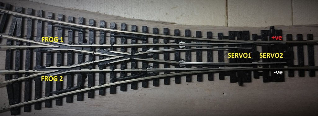
Let me see if I can explain how I figured out how it works so I could wire it up.

I’ve nominated the lower track to be negative (-ve) and the upper track to be positive (+ve) for the sake of this discussion. So long as they don’t short circuit, everything comes up roses.
Servo1 and Servo2 drive the points. Frog1 powers the centre and the right-hand turnout. Frog2 powers the centre and the left hand turnout.
There are three possible values for the position of the servos as set out in the table below (You cannot have servo1 up and servo2 down). I have written down the required polarity of each frog based on which turnout is active.
| Servo position | ↑ ↑ (left) | ↓ ↑ (centre) | ↓ ↓ (right) |
| Frog 1 | n/a | +ve | -ve |
| Frog 2 | +ve | -ve | n/a |
When the turnout is in the left position (↑↑), the polarity of FROG1 is unimportant. Likewise when the turnout is in the right position (↓↓), the polarity of FROG2 is unimportant.
It can be seen that there is a relation between Servo1 and Frog 2 and between Servo2 and Frog1, such that
Frog1 polarity must be +ve when Servo2 is up and -ve when Servo2 is down.
Frog2 polarity must be +ve when Servo1 is up and -ve when Servo1 is down.
The microswitches attached to the servos are activated when the servo has moved the switch to the right. This gets a bit tricky now because I have the servos mounted facing each other, not back to back, so that there’s plenty of room to work with them.
The microswitches have three pins. two of them are connected to +ve and -ve inputs. The third pin is the output and will be either +ve or -ve depending on the state of the switch. I mapped which pin would be active on the switch based on the position of the servo in relation to the track.
| Servo position | ↑ | ↓ |
| Servo 1 microswitch pin active | pin 1 | pin 2 |
| Servo 2 microswitch pin active | pin 2 | pin 1 |
I determined that when Servo1 was in the up position, it’s microswitch was connecting pin 1 to common. As the servos are reversed in relation to each other, the opposite it true of Servo2.
The microswitches are wired as follows:
| Microswitch | pin 1 | pin 2 | pin 3 |
| servo 1 connected to Frog 2 | +ve | -ve | common |
| servo 2 connected to Frog 1 | -ve | +ve | common |
So, for example, when both servos are thrown to the left, the turnout is to the right, and Frog1 needs to be -ve polarity. Frog1 is connected to the microswitch on servo2 which is down, so pin 1 is connected to common so the frog is -ve.
