Wireless connection rethink

Ok, so I’ve been working on getting my wireless shield working on my DCC++ project and I finally came across information which leads me to believe that pin 13 is still not usable on the CC3000 shield even when used with the Mega2560!

I can connect to my home network no problem, but comms are just not working no matter what I do.

I’m going to have to break the problem down into parts – testing the CC3000 shield on it’s own to start with. Just need some time to get into it…

Arduino WiFi shield

I just realised I haven’t blogged now for over a month!

Life has been very busy with work and stuff and this project has taken a back seat. That’s ok with me as I don’t want to just charge into this and finish it all because then all the fun is over.

I’ve been working (in my free time) on getting the WiFi shield integrated into the DCC++ base station code. It’s currently connecting to my home WiFi network and I can ping it successfully but it’s not accepting a client connection using telnet. I’ll probably have some time to work on that over Easter – probably only needs a couple of hours.

I’ve also started looking into detection hardware so I can tell when a locomotive or car passes a point on the track. Looks like RFID is the best solution but I’m holding off until I finish the WiFi connection.

Points are switching

I got back onto the points this morning and after a fair bit of messing about figured out that you have to program the Arduino with the points it will switch using this command

<T id addr offset>

for each of the points where id is the id referenced in the controller and addr and offset are the physical address of the point. Once they are all set, then issue

<E>

to write the data to the Arduino EEPROM.

These values can be written using the serial monitor in the Arduino software.

Doing this enables the Controller to send <T id n> to the base station to activate the point servo with ID id where n is 1 or 0 to set or unset the point.

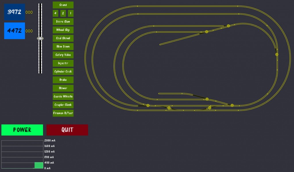
The controller software now looks like this. I’ve changed the look of the track (so it looks more like track) and I’ve made the switches show up on the layout so I can see where to click.

DCCpp_Controller2

Bluetooth … Harold is not happy

I purchased a Bluetooth module to attach to the Arduino today. I connected the leads from it GND – GND, 3.3V – 3.3V, RX – TX, TX – RX. I got the little flashing red light happening on the Bluetooth module, but no communications. In fact, it kept locking up the program which was a bit of a nuisance.

Ah well! The best laid plans of mice and men as they say… I screwed the Ardui-Motor to the table so I could make safer semi-permanent connections and got the locomotives moving again. This time, I also connected DCC power and set the jumper on the Octocoder and got the turnouts running under computer control! Unfortunately I have 11 turnouts and the Octopus3 will only run 8 of them at a time, so I’ll eventually have to get another Octopus3 to complete the setup. That’s ok because I plan to have an additional 4 turnouts on the layout yet.

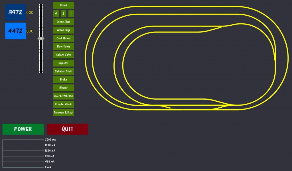
This is the DCC++ Controller screen on my PC. I’ve diverged from the codebase pretty substantially.

DCCpp_Controller screen

I’m very still pleased to see that I don’t need an expensive controller to run things. Hooray for Arduino and DCC++ (Thanks Gregg)!

I jury rigged my Surface Pro 3 & Ardui-motor to the track

I had it all working – the controller was successfully running my two locomotives. I had the sound running and the horns blowing just by pressing buttons on the screen. Then something happened and everything went dark – I think the Arduino shorted across the programming track.

For about five minutes I thought I’d destroyed the Surface Pro 3 but luckily a hard-restart has brought it back to life.

So the next part of the plan is going to be figuring out how to mount all the component parts at the table so this does not happen again  😛  I’d love to bluetooth connect to the Arduino, but that’s going to have to wait until I can get another power supply to power it.

Power supply count is currently at two (one 14VDC for point motors and another 14VDC to power DCC)

Programming Track is working

For some reason, I had connected pins 4 & 13 on the arduino instead of pins 2 & 13. This exhibited the following behaviour:

  • DC 14.8V output to track
  • Only one programming track light was lit on the motor shield
  • Putting the loco on the programming track set it running when POWER button was pressed.

I’ve now successfully programmed the two locomotives I have on hand with their long addresses (3972, 4472).

Next task is to connect the arduino to the layout and see if it drives it!

Last servo working and controller set up

I was about ready to pull the servo from under the table this morning, when I thought I should check the new servo extension cable first – lucky I did because that was the issue. New cable in and it’s all apples again!

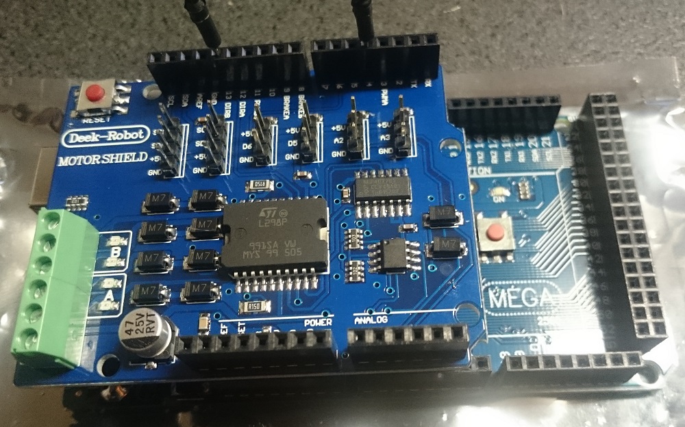
My next task was to cut the voltage connector on the Arduino (Deek-Robot) Motor Shield which ordinarily supplies current to the Arduino so I can use higher voltage on the Motor Shield required by DCC. Then I mounted the Motor Shield on the Arduino and connected pins 4 & 13 as required to generate a DCC signal.

After that, I recompiled the Base Station Master DCC++ code and loaded it into the Arduino’s memory.

Finally, loading my customised controller layout in Processing, I was able to connect to the Arduino via the USB port. The only trouble I had here was in connecting, but then I re-read the instructions, pressed ‘s’ to bring up the connection options, selected COM3 and voila, the software successfully connected and displayed the results.

Now all I need is a 14V DC power supply…

Final point switches & servos

I’ve just wired up the last five servos & microswitches under the table. I hadn’t considered how much of a nuisance it would be soldering & heat-shrinking wires under a table and above my head. It gets pretty hot under there and the halogen light I was using for illumination wasn’t helping. Anyway, all the servos are in and all but one are working great. The last one can wait until later – I need a drink!

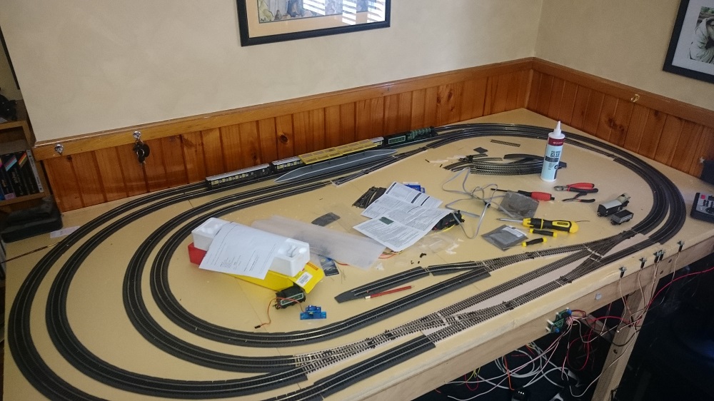
This is what it looks like now – those wires you can see under the table are all tidied away now. The TAM Valley Octopus3 is mounted to the side of the table for now.

DSC_0678

Servos are all installed

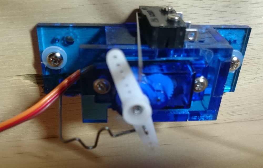
I’ve just finished installing the remaining servos and aligning them. My biggest problem was how to mount the servos when they are close to a support timber under the table. I spent some considerable time looking around the internet at other people’s solutions and finally came up with this one. It employs a right angle bend and one of the other holes in the servo holder. I added a wavy “spring” section since there will be a twisting force at the right angle bend.  The wire is bent underneath the actuating arm to hold it in place.

Servo Sideways

The next task is to wire up all the micro switches to power the frogs. I’ll get onto soldering these later.