Points are switching

I got back onto the points this morning and after a fair bit of messing about figured out that you have to program the Arduino with the points it will switch using this command

<T id addr offset>

for each of the points where id is the id referenced in the controller and addr and offset are the physical address of the point. Once they are all set, then issue

<E>

to write the data to the Arduino EEPROM.

These values can be written using the serial monitor in the Arduino software.

Doing this enables the Controller to send <T id n> to the base station to activate the point servo with ID id where n is 1 or 0 to set or unset the point.

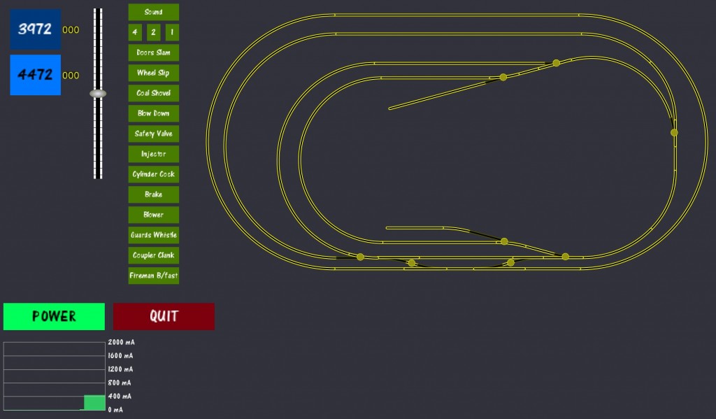
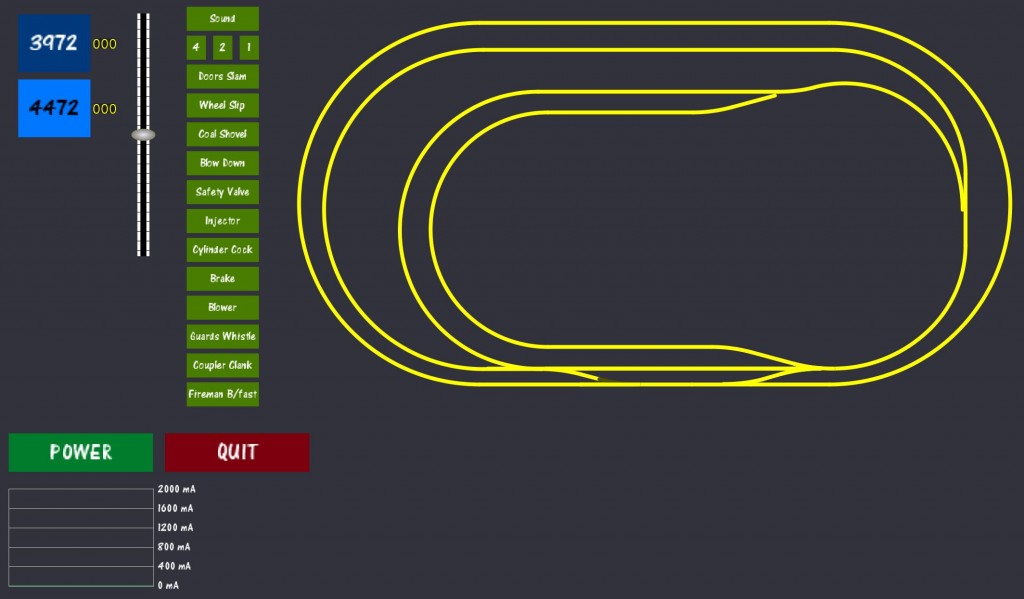
The controller software now looks like this. I’ve changed the look of the track (so it looks more like track) and I’ve made the switches show up on the layout so I can see where to click.

DCCpp_Controller2

Bluetooth … Harold is not happy

I purchased a Bluetooth module to attach to the Arduino today. I connected the leads from it GND – GND, 3.3V – 3.3V, RX – TX, TX – RX. I got the little flashing red light happening on the Bluetooth module, but no communications. In fact, it kept locking up the program which was a bit of a nuisance.

Ah well! The best laid plans of mice and men as they say… I screwed the Ardui-Motor to the table so I could make safer semi-permanent connections and got the locomotives moving again. This time, I also connected DCC power and set the jumper on the Octocoder and got the turnouts running under computer control! Unfortunately I have 11 turnouts and the Octopus3 will only run 8 of them at a time, so I’ll eventually have to get another Octopus3 to complete the setup. That’s ok because I plan to have an additional 4 turnouts on the layout yet.

This is the DCC++ Controller screen on my PC. I’ve diverged from the codebase pretty substantially.

DCCpp_Controller screen

I’m very still pleased to see that I don’t need an expensive controller to run things. Hooray for Arduino and DCC++ (Thanks Gregg)!

Final point switches & servos

I’ve just wired up the last five servos & microswitches under the table. I hadn’t considered how much of a nuisance it would be soldering & heat-shrinking wires under a table and above my head. It gets pretty hot under there and the halogen light I was using for illumination wasn’t helping. Anyway, all the servos are in and all but one are working great. The last one can wait until later – I need a drink!

This is what it looks like now – those wires you can see under the table are all tidied away now. The TAM Valley Octopus3 is mounted to the side of the table for now.

DSC_0678

Servos are all installed

I’ve just finished installing the remaining servos and aligning them. My biggest problem was how to mount the servos when they are close to a support timber under the table. I spent some considerable time looking around the internet at other people’s solutions and finally came up with this one. It employs a right angle bend and one of the other holes in the servo holder. I added a wavy “spring” section since there will be a twisting force at the right angle bend.  The wire is bent underneath the actuating arm to hold it in place.

Servo Sideways

The next task is to wire up all the micro switches to power the frogs. I’ll get onto soldering these later.