Wireless connection rethink

Ok, so I’ve been working on getting my wireless shield working on my DCC++ project and I finally came across information which leads me to believe that pin 13 is still not usable on the CC3000 shield even when used with the Mega2560!

I can connect to my home network no problem, but comms are just not working no matter what I do.

I’m going to have to break the problem down into parts – testing the CC3000 shield on it’s own to start with. Just need some time to get into it…

Bluetooth … Harold is not happy

I purchased a Bluetooth module to attach to the Arduino today. I connected the leads from it GND – GND, 3.3V – 3.3V, RX – TX, TX – RX. I got the little flashing red light happening on the Bluetooth module, but no communications. In fact, it kept locking up the program which was a bit of a nuisance.

Ah well! The best laid plans of mice and men as they say… I screwed the Ardui-Motor to the table so I could make safer semi-permanent connections and got the locomotives moving again. This time, I also connected DCC power and set the jumper on the Octocoder and got the turnouts running under computer control! Unfortunately I have 11 turnouts and the Octopus3 will only run 8 of them at a time, so I’ll eventually have to get another Octopus3 to complete the setup. That’s ok because I plan to have an additional 4 turnouts on the layout yet.

This is the DCC++ Controller screen on my PC. I’ve diverged from the codebase pretty substantially.

DCCpp_Controller screen

I’m very still pleased to see that I don’t need an expensive controller to run things. Hooray for Arduino and DCC++ (Thanks Gregg)!

I jury rigged my Surface Pro 3 & Ardui-motor to the track

I had it all working – the controller was successfully running my two locomotives. I had the sound running and the horns blowing just by pressing buttons on the screen. Then something happened and everything went dark – I think the Arduino shorted across the programming track.

For about five minutes I thought I’d destroyed the Surface Pro 3 but luckily a hard-restart has brought it back to life.

So the next part of the plan is going to be figuring out how to mount all the component parts at the table so this does not happen again  😛  I’d love to bluetooth connect to the Arduino, but that’s going to have to wait until I can get another power supply to power it.

Power supply count is currently at two (one 14VDC for point motors and another 14VDC to power DCC)

Programming Track is working

For some reason, I had connected pins 4 & 13 on the arduino instead of pins 2 & 13. This exhibited the following behaviour:

  • DC 14.8V output to track
  • Only one programming track light was lit on the motor shield
  • Putting the loco on the programming track set it running when POWER button was pressed.

I’ve now successfully programmed the two locomotives I have on hand with their long addresses (3972, 4472).

Next task is to connect the arduino to the layout and see if it drives it!

Last servo working and controller set up

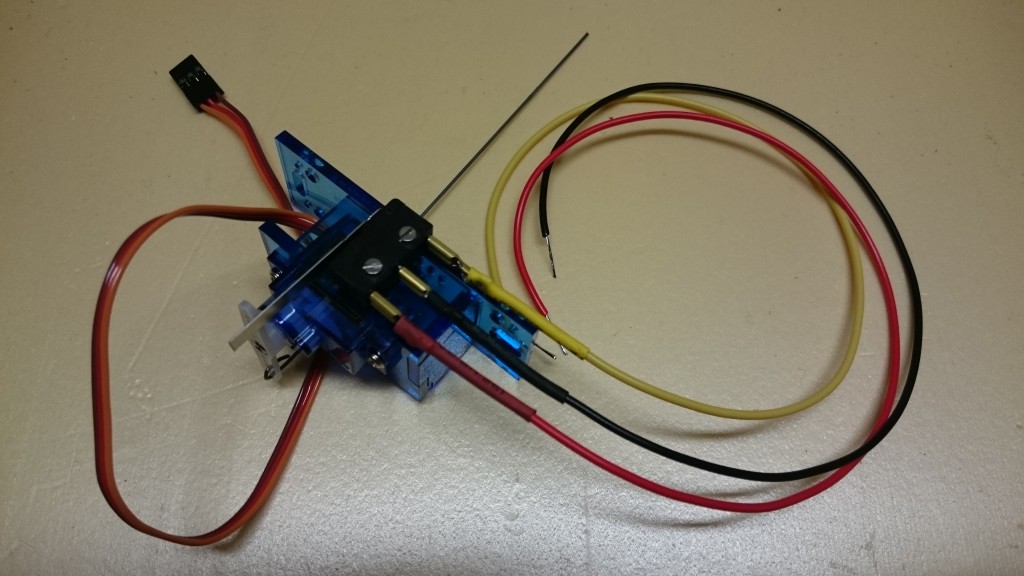
I was about ready to pull the servo from under the table this morning, when I thought I should check the new servo extension cable first – lucky I did because that was the issue. New cable in and it’s all apples again!

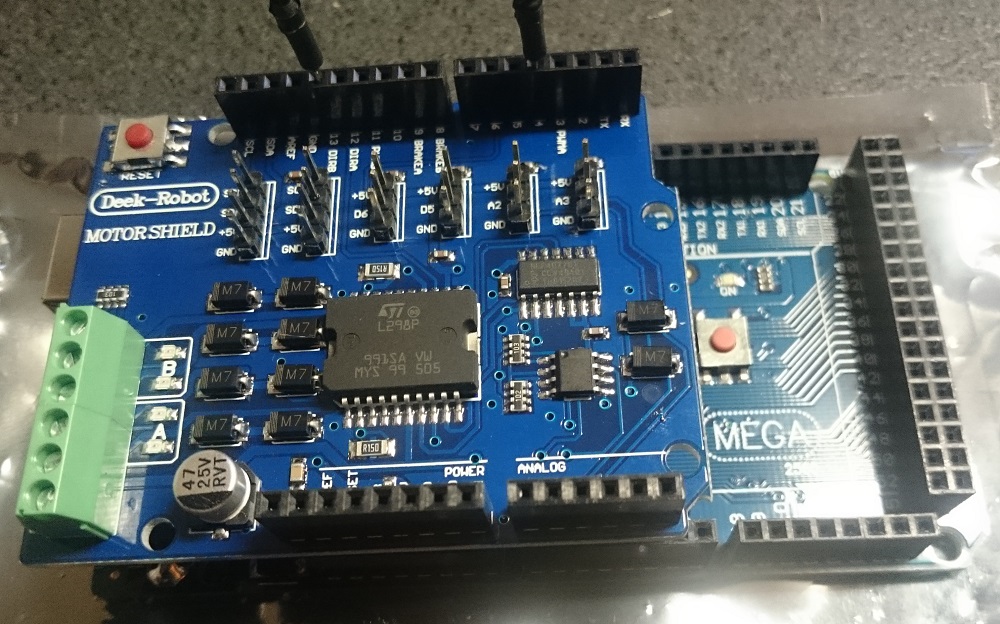
My next task was to cut the voltage connector on the Arduino (Deek-Robot) Motor Shield which ordinarily supplies current to the Arduino so I can use higher voltage on the Motor Shield required by DCC. Then I mounted the Motor Shield on the Arduino and connected pins 4 & 13 as required to generate a DCC signal.

After that, I recompiled the Base Station Master DCC++ code and loaded it into the Arduino’s memory.

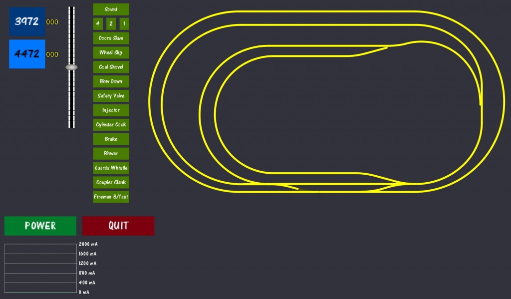
Finally, loading my customised controller layout in Processing, I was able to connect to the Arduino via the USB port. The only trouble I had here was in connecting, but then I re-read the instructions, pressed ‘s’ to bring up the connection options, selected COM3 and voila, the software successfully connected and displayed the results.

Now all I need is a 14V DC power supply…

Arduino & more

I’ve spent the last few days reading up about Arduino, how DCC works, DCC++ and how it all works together. I’m excited to say that I’ve purchased an Arduino Mega and a Motor Shield to start the process of computer control of my DCC layout.

I’m ordering an Octocoder today (hopefully) to go with my TAM Valley Octopus3 to enable DCC control as well.

Still waiting on servos & servo extensions to arrive from China…

The more I research DCC computer control, the more I’m astounded by how much there is available for it, either customisable or off the shelf.

More details to come when I get it all assembled.

UPDATE: Servos have arrived – getting closer
UPDATE: Arduino Mega has also arrived today – fast delivery!

Slow couple of weeks – and a Flying Scotsman!

I’ve been taking a break over the Australia Day holiday – and waiting for some bits and pieces to arrive from China, namely servos and servo extension leads to finish the project.

In the meantime, I’ve made up the remaining five servo mounts which I purchased from Brunel Hobbies. I’ve got to purchase some clevises and pushrods because three of the remaining servos are to be mounted in a restricted space, though they’ll only be an inch or two away from the spot they are needed.

I purchased the Hornby Flying Scotsman with DCC Sound yesterday too when I was in the shop and have had it running around and around on the track choo-chooing and whistling away. I’m such a kid!

Wiring the microswitch

I’ve made three wires to attach to the microswitch – red and black are the inputs and yellow is the output. When the switch is open, the yellow wire will be one polarity and when closed it will be the other. If it’s the wrong way around, I’ll simply swap the black and red wires (which are thankfully the easiest two to get to)

The black and red wires take their input from the DCC bus. The yellow wire will go to one of the frogs on the three-way turnout.

Microswitch leads

To determine which wire goes where, I drew a diagram which showed all the parts and then calculated the frog polarities. Each of the frogs is powered from one microswitch.

Servos and octopuses

Yesterday I took the plunge and purchased a couple of servos, a TAM Valley Octopus IIIa Servo Driver, switches and a remote aligner. I’ve started putting it all together – the servos are mounted in their brackets and I have cut and bent the piano wire onto them.

Servos

I’ve removed the springs from the point that I’m going to wire up also so it’s all ready to go. I’m seriously considering putting a 10mm brass sleeve inside the hole for the servo wire to pass through. I will get onto it later today when I have some time – I have some other things I need to attend to first.